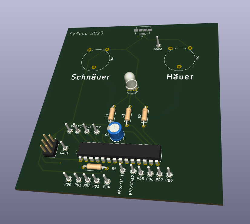
For a local school project I designed a little soldering task revolving around story about an extraterrestrial species who left a piece of tech (the PCB to assemble). The PCB itself is an atmega8 controlling a single RGB LED. Two potentiometers set the brightness (“Häuer” which means “brighter” in swissgerman, and “Schnäuer” which means faster in sg) and speed of a hue shift effect.
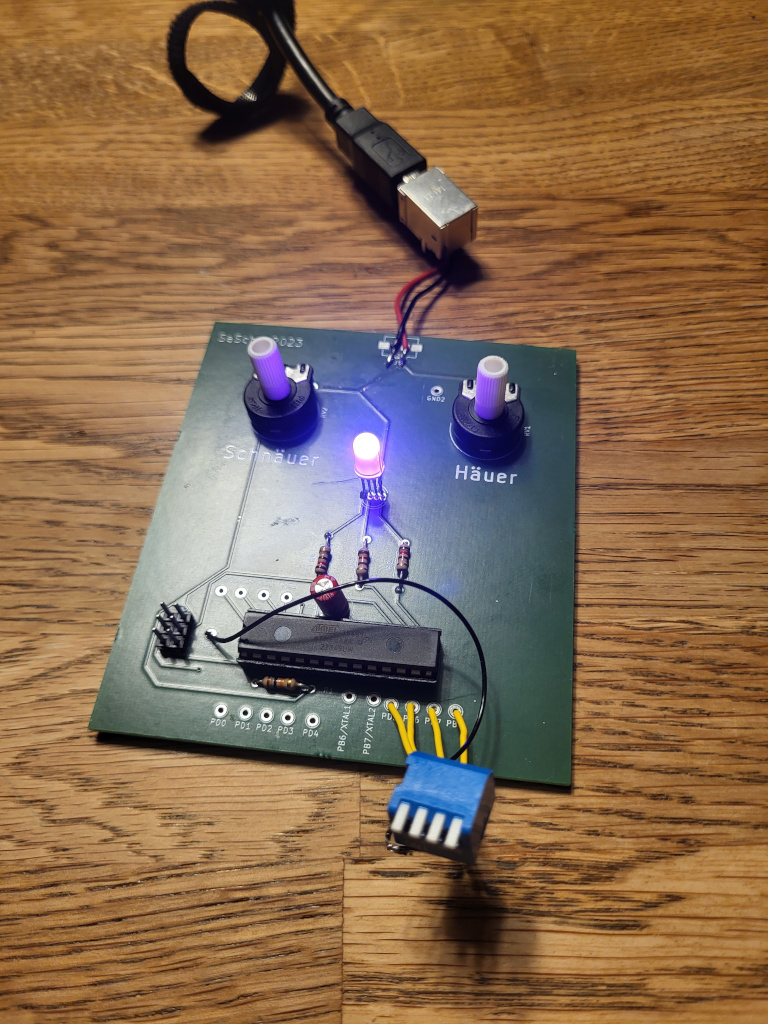
By successively adding switches to certain pins the student can gradually unlock additional functionality, eventually find the LED to be blinking in a Morse pattern which they can decode.
The projected is intended for a group of 9-12 jears old kids for a group of around 8 kids per instructor taking half a day for completion.
Required Material
- PCB with Micro-USB connector presoldered
- Atmega8, Resistors, LED, Capacitor (see parts list below)
- Soldering Iron
- Solder
- Switches
- Wirecutter
- Wire Stripper
- Desoldering pump and/or desolder wick
- A few USB-Powerbanks
- Arduino as AVR-Programmer
- PC able to transfer the firmware
Parts List
- 3x 120 Ohm Resistor
- 1x 10 kOhm Resistor
- RGB Led, Common Anode, Layout BGAR (Pin1: Blue, Pin2: Green, Pin3: Anode, Pin4: Red)
- 2x 22k Piher Potentiometers
- 1x 1uF polarized Capacitor, 16v or higher
- 1x Atmega8, DIL-28 Format
- 2.54mm Pinheader
Resources