For a local arts workshop i’ve been building a analog echo machine which uses standard compact cassettes. Some part have been taken from old salvages tape decks, while others have have been bought as new. The electronics have been designed partly using resources on the internet with a good dose of trial and error / research since many schematics used hard-to-get parts. Also, I wanted to have it powered of a simple 9v source. For such a power supply scenario not many schematics are available on the web. This page describes the build procedure, error made and knowhow gathered hoping to facilitate build for other who want to build a “modern” analog tape delay using inexpensive, and for the most part, readily available parts.
Schematic
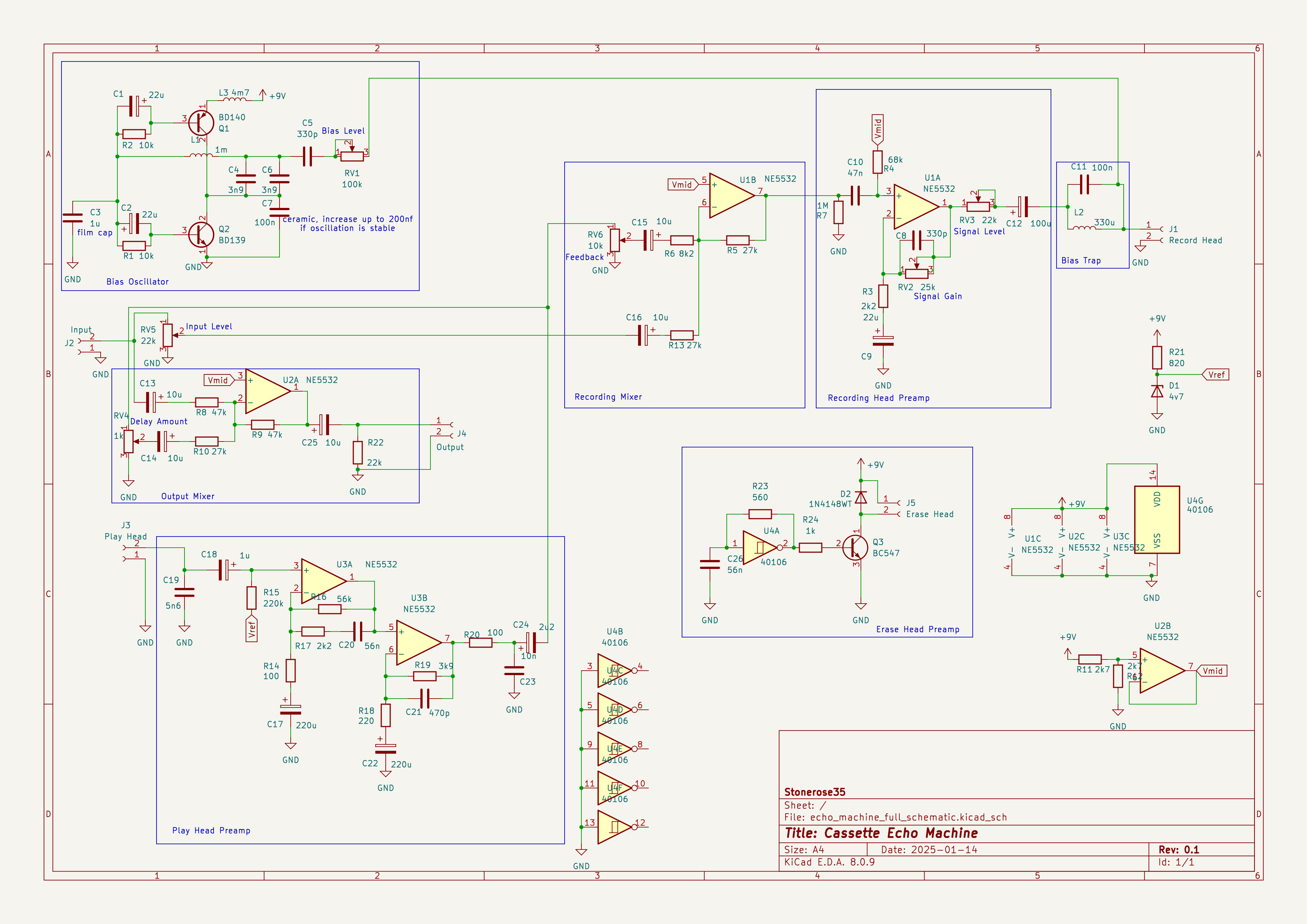
The schematic faithfully represents the actual unit build. It is far from optimal regarding package choices and parts count but has proven to be working. In the sections below the individual parts are described in more detail.
Mechanics and Reading Tapes
The basis of a tape delay is of course magnetic tape, moving at a constant speed, preferably with only a small charming amount of wobbling. Since we had a broken hifi set laying around we decided to extracted the tape mechanics. I first though that the shafts that rotate the tape reels are responsible for the progapation of the tape. A good friend of mine has proven me wrong by explaining that a small metal rod along with a rubber wheel moves the wheel. Having this sorted out I thought it is easiest to design a freeform tapeloop running around those little guiding wheels found in compact cassettes mounted on small pieces of wood.
Next up designing the mechanical layout was the placement of the head. I wanted to have a delay time um round 1/4 to 1/2 of a second. With a tape speed of 5cm/s this results in a head spacing if approximately 1.5cm.
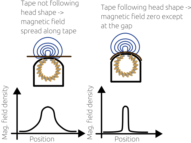
For sake of mechanical simplicity I first let the tape run along a straight line along the curved head. The idea was to reduce friction a much as possible. When experimenting with the setup I was always confronted with a faint and, most importantly dull sound. I carefully worked on the alignment, made sure I was playing back the right side of the tape and that the vertical alignment of the tape was correct. After much experimentation I empirically found out that the sound got better the more the tape follows the curvature of the tape, also friction between the tape head an the tape has proved to be less of an issue as expected.
The explanation for this behaviour I think is due to the distribution of the magnetic field. When reading information from the magnetic field on the tape is convolved with the magnetic field from the coil around a circular ferrite element with the small gap. With the enclosure of the tape head being grounded the strongest sensivity is at the gap with magnetic field lines circulating around it. When the tape runs in a straight line the magnetic field density is spread over a wider space thus averaging out field changes on the tape occurring on a smaller distance. Given a tape speed v the extent of a period of a signal at a fixed frequency f_sig is given by
Therefore, the greater the frequency the smaller the distance to encode this signal on the tape.
Schematic / Electronics
The schematic (see “Play Head Preamp” above) is in large parts taken from https://sound-au.com/project247.htm, with a few modification made for single supply and signal levels. Since the voltage gain needs to be around 80-90dB it is important to use low-noise Op-Amps to avoid having broad-frequency noise. To suppress hum and spurious interferences the paths from the tape head to the preamp needs to be shielded, including grounding the tape head.
Important findings
- Follow the head curvature with the tape
- Avoid oscillations of the tension of the tape -> damp springs which tighten the tape, or use a springless setup
- ground tape heads, used cable with good shielding from the tape head to the preamp
- Use Low-Noise Opamps for the playback preamp
- Carefully lay out the mechanical setup, at track on a compact cassette is only 1mm wide!
Writing Tapes
Writing a signal onto magnetic tape requires some more effort. This is due to the so-called “Tape Bias”. Because a permanent magnetization requires imposed magnetization to overcome a minimum level the audio signal is superimposed with a sine signal of a frequency above audio range.
To generate sign high-frequency signal i used a schematic for a sine oscillator found here https://content.instructables.com/F1P/UFML/KTCA1328/F1PUFMLKTCA1328.pdf with a few modifications (see “Bias Oscillator” above).
- A dedicated inductor was used instead of the erase head. First,i didn’t have an erase head at all, then it didn’t work with the one to got from a tabletop cassette deck.
- A inductor was added at the power supply rails to avoid bleeding of the high-frequency signal to the power rails
- The Capacitors C3, C4, C6 and C7 have to be selected carefully. Especially C7, the higher the value the higher the signal level – until the oscillation stops
The Recording preamp is a standard op-amp based gain (see “Recording Head Preamp” above), C10 and R4 form a highpass with cutoff frequency 49.8Hz to avoid low-frequent rumbling and hum to be recorded onto the tape. At the output C11 and L2 form a parallel resonator ideally at the frequency of the bias signal prohibiting feedback of the bias-signal into the recording preamp.
Both signal and bias level can be adjusted using potentiometers. Bias almost fully up and signal level at a third has prove to be the best option.
Erasing Tapes
Since I couldn’t integration the erase head into the oscillator circuit i had to come up with another design to erase the tape before each write-read cycle. First I started by placing the unpowered erase head i got from the broken hi-fi deck. This erased tape but added some kind of grainy noise which got worse with each cycle. Also, the recording got more and more distorted each time. Obviously (in retrospective) the constant magnetization maybe allowed 3-4 rewrites with reasonable quality which was probably enough for a hi-fi tape deck. But not for a loop-based tape delay..
So a I had to come up with a simple design which works at 9v and doesn’t require fancy component. Many source on the internet state that a sine has to be used for erasing, so I tried simply to recreate the write circuit with the idea that writing “zero” would be equal to erasing. Unluckily, the signal was too weak. The I came across the schematic of a wem copycat, some i believe is a square wave oscillator going through a transformer afterwards is used a high-frequency signal both for bias and erasing. This encouraged me to try out a simple inverter-based squarewave-oscillator at around 25kHz. A added a transistor stage which simply turn on the full current for every positive half wave. A shunt diode had to be added to allow the current to flow back when the transistor is off. Like this the maximum current is sucked through the erase head given the 9V power supply. I was expecting that i needed to add a a transformer but this wasn’t the case. The erase signal has finally proven to be good enough to first of all erase the tape and to conserve the magnetic properties for recording many times.